Dice Roller
These are design notes for the construction of a digital dice display made from a 3x3 matrix of leds for each die. I was inspired by Dave's success building other cybords and his suggestion above. -- WardCunningham
We will number the leds 1 through 9, and illuminated them one at a time in the following patterns.
     1 . 7
     2 . 8  =>  6
     3 . 9
     1 . 7
     . 5 .  =>  5
     3 . 9
     1 . 7
     . . .  =>  4
     3 . 9
     . . 7
     . 5 .  =>  3
     3 . .
     1 . .
     . . .  =>  2
     . . 9
     . . .
     . 5 .  =>  1
     . . .
Leds 4 and 6 are not illuminated by any of these patterns. However, if we include 90 degree face rotations we'll be able to use all nine of the leds by casting dice in all orientations.
If we unwind these patterns we get the following 12 variations, again with some duplication.
     1  2  3  .  .  .  7  8  9  => 6
     1  .  3  .  5  .  7  .  9  => 5
     1  .  3  .  .  .  7  .  9  => 4
     .  .  3  .  5  .  7  .  .  => 3
     1  .  .  .  .  .  .  .  9  => 2
     .  .  .  .  5  .  .  .  .  => 1
     1  .  3  4  .  6  7  .  9  => 6'
     1  .  3  .  5  .  7  .  9  => 5'
     1  .  3  .  .  .  7  .  9  => 4'
     .  .  3  .  5  .  7  .  .  => 3'
     .  .  3  .  .  .  7  .  .  => 2'
     .  .  .  .  5  .  .  .  .  => 1'
Notice that leds 1 and 9 are always on at the same time. Same for three other combinations yielding the equivalences noted in the following table.
                v   d
     1 == 9 => 001 001
     2 == 8 => 000 001
     3 == 7 => 010 010
     4 == 6 => 000 010
     5 == 5 => 100 100
For each of these five variations, we'll either source or sink current so as to further multiplex the three available output pins. For each pin we encode a value (v) and a data direction (d). We'll use this to drive a circuit like the following where each V represents an led.
     ;           +-----+-----+-----+----------- vcc
     ;           |     |     |     |
     ;           V2    V8    V4    V6
     ;           |     |     |     |
     ;   p2 -----|-----|-----|-----|-----x
     ;           |     |     |     |     |
     ;   p1 -----|-----|-----x-----x     |
     ;           |     |     |     |     |
     ;   p0 -----x-----x     |     |     |
     ;           |     |     |     |     |
     ;           V1    V9    V3    V7    V5
     ;           |     |     |     |     |
     ;           +-----+-----+-----+-----+----- gnd
We'll pulse current through one led (or led pair) at a time. A pattern of five bits will encode if a channel is needed for any particular die face.
     11100 ;6
     10101 ;5
     10100 ;4
     00101 ;3
     10000 ;2
     10110 ;6'
     10101 ;5'
     10100 ;4'
     00101 ;3'
     00100 ;2'
     00001 ;1'
This pseudo code describes the loops we will need to generate appropriate bit sequences from the above tables.
     repeat
     	acc += speed
     	++face %= #faces if overflow
     	pat = faces[face]
     	repeat i = 1..5
     		on = shift(pat)
     		out = on ? outs[i] : 000 000
                delay 1 msec
     	end
     end
Shuffle
Additional randomness could be achieved by storing many multiples of each face in the face table and shuffling the table in the source code. The shuffling would have some constrains. We wouldn't want a run of the same face, for example, or for two faces to alternate for two long. A more appropriate shuffle might be achieved by some Markov like process that adjusts conditional probabilities. We will still call this a shuffle because each face must be equally present, otherwise we have loaded dice.
I asked the attendees at BeaverBarCamp to help me come up with these statistics. I coded one of their solutions (see page for program) and found this result for five of each face: 612643514261451452354256326531436132
While spinning, it would be nice if the leds flickered at uniform brightness. This could be achieved by padding the face table with complementary faces that could be ignored when spinning below some threshold speed.
Construction
We'll use a daughter card to hold the nine leds. We'll feed p0, p1, p2, vcc and gnd to this card through a header that will plug directly into the device side of the computer. The fifth pin, gnd, will require routing one wire on the prototyping board to complete the circuit.
The daughter card will be cut from prototyping board preserving 6 by 6 intact holes. See CuttingCircuitBoard. Through-hole plated prototyping board is recommend so that parts can be soldered into place before the daughter card is wired.
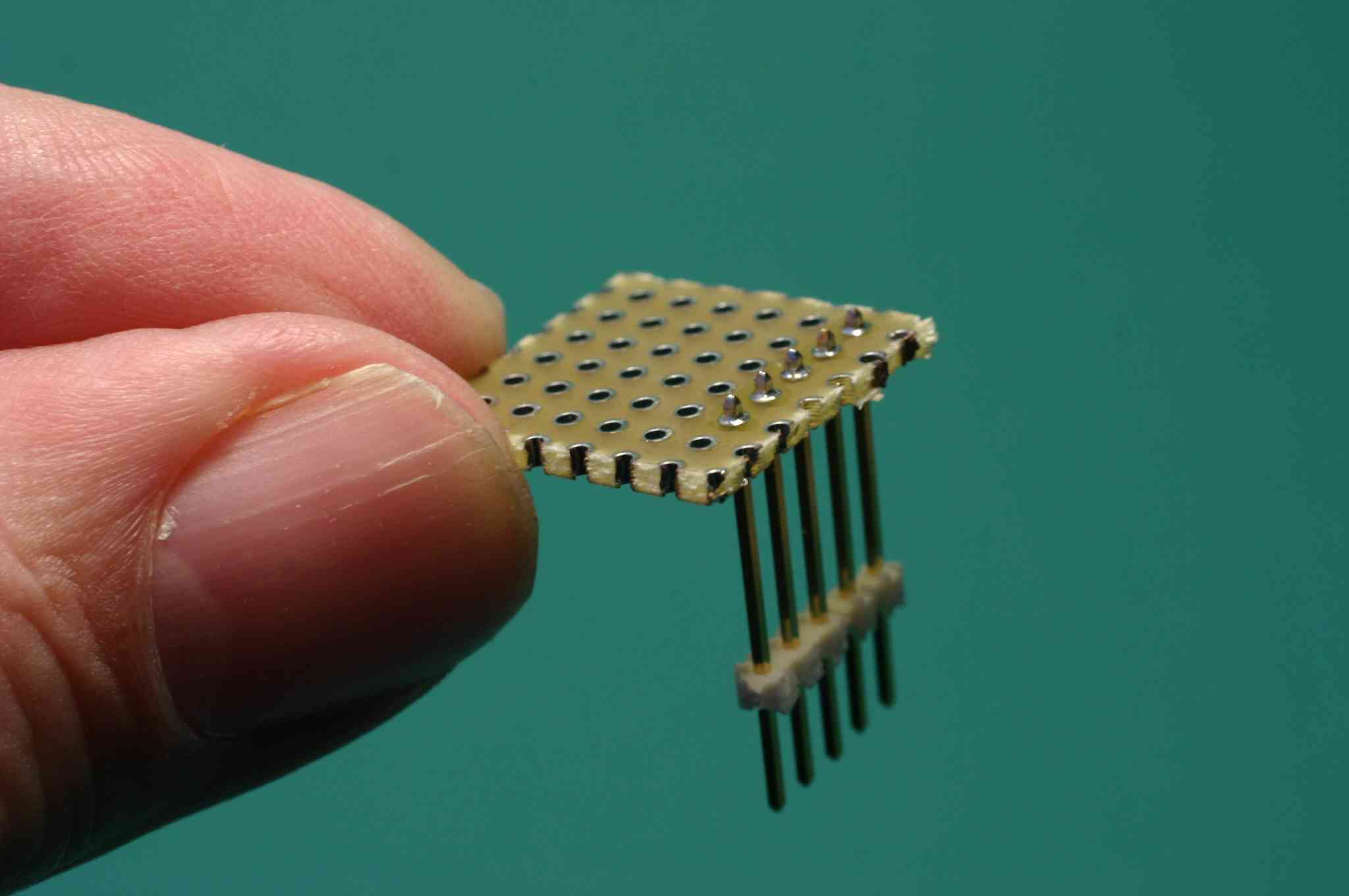

This diagram is a physical version of the above schematic. (click to enlarge)

The point-to-point wiring can be done by soldering through the insulation of fine wire-wrap wire. Wire vcc and gnd first. They are easier to get right and together will touch one lead of every led.

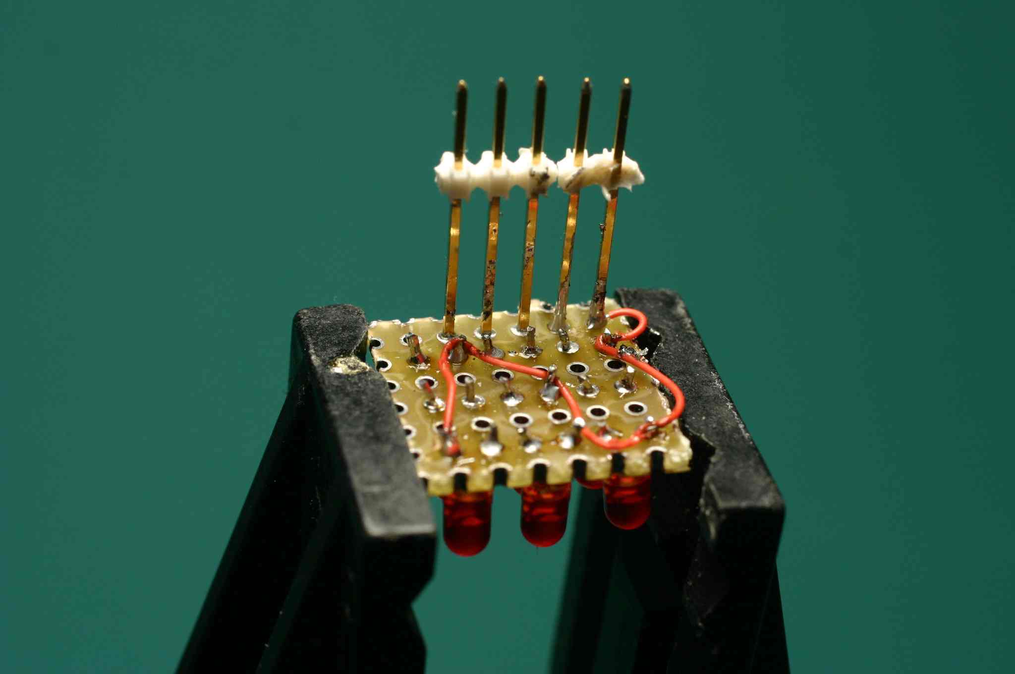
Idea: With unused columns in the middle of the led layout, there is no need to add one more column for the header. Instead, squeeze it between the lights. ... No, this is a bad idea. The led card and the BreadboardSpider will fit together, but only if the led card is built as designed.
Test the board by connecting 3v from vcc to gnd. All leds remain off. Pairs of leds should illuminate by connecting one of p0, p1 or p2 to vcc or gnd. Led 5 is the only one that should illuminate individually.

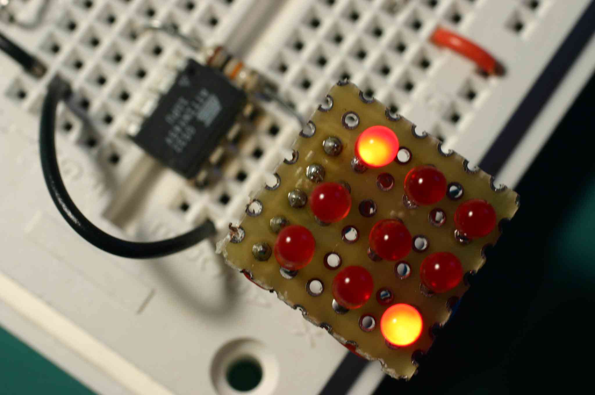
While testing I observed a faint background glow even when leds were off. This is because there is a closed circuit through most of the leds even when the computer is not pulling up or down. The effect is more noticeable at higher vcc voltages. It goes away with vcc = 2 volts, which is below the two diode drops present in the unwanted paths.
Circuits
The outer loop switches between faces at a variable speed. If speed is zero, a single face will show. A cybord circuit might use a descending RampPulseGenerator to create the effect of rolling a die. One ramp could control multiple dice, each with their own clock, and therefore a suitably random result for most games of chance.
     Ramp --+--> Die
            |
            +--> Die
Ultimately we'd need some sort of trigger circuit for the Ramp so the dice roll on demand. The Ramp part has plenty of unused pins.
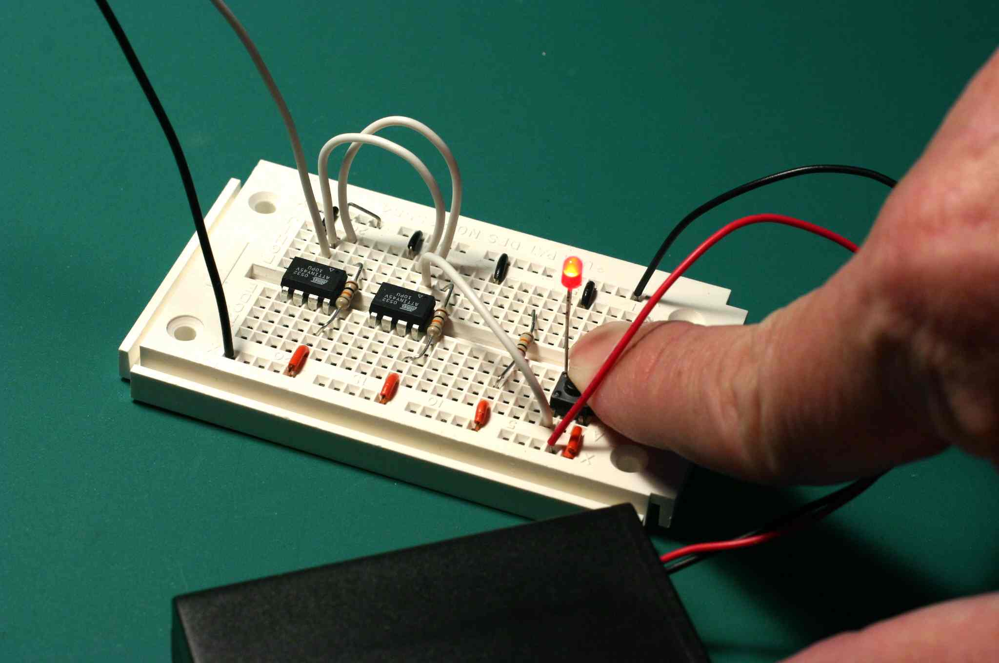
Or a simple button would work. Here I use a push button to the pi up to vcc and a led to pull down to gnd.
The Die's po pin is not yet used. It is only natural that it output 0, 20, 40, 60, 80, or 100% corresponding to which ever face happens to be showing. An interesting circuit might be to draw random scribbles by incorporating dice into the ScribblerProject. An AnalogKnobConverter would control the scribble rate of two dice, each driving their own ServoMotor, one for r, the other theta.
     Knob --+--> Die --> Servo
            |
            +--> Die --> Servo
Multiple Dice can be hooked in parallel with their outputs summed to get a random variables with approximately Gaussian statistics by the central limit therom and the BynaseProtocol's unique summing properties.
  ;         +--> Die --+
  ;         |          |
  ;     ----+--> Die --+--->
  ;         |          |
  ;         +--> Die --+
These pictures show that this does indeed work. Using two parts (see above) I was able to observe eleven distinct states by recording tick marks on a sticky-note each time I released the button.
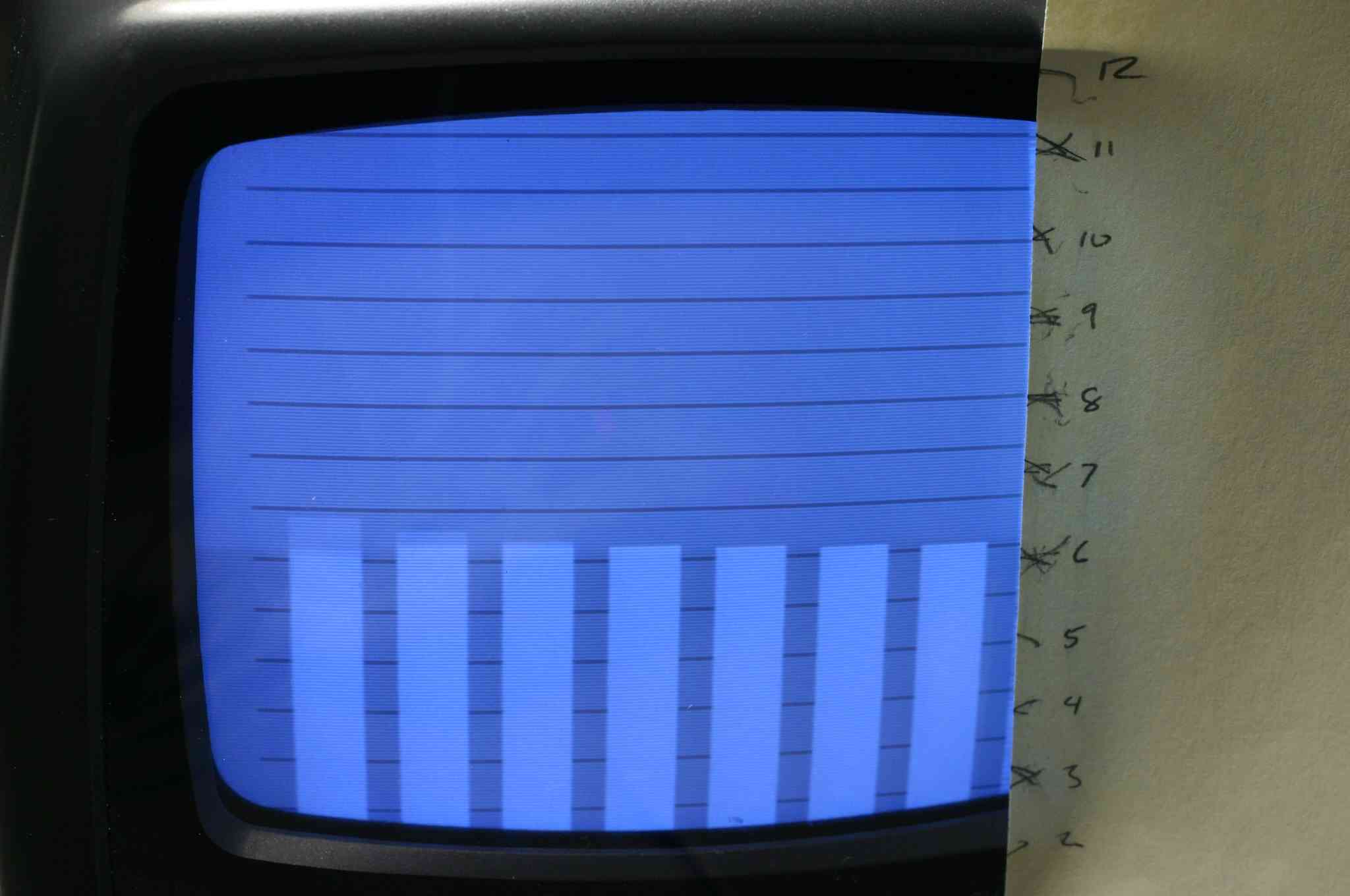

Here we see the dice stopped in two different states, one adding up to six, the other, nine.
This part is still a work in progress, but we are happy to share our work so far.
Return to WelcomeVisitors