Solderless Breadboard
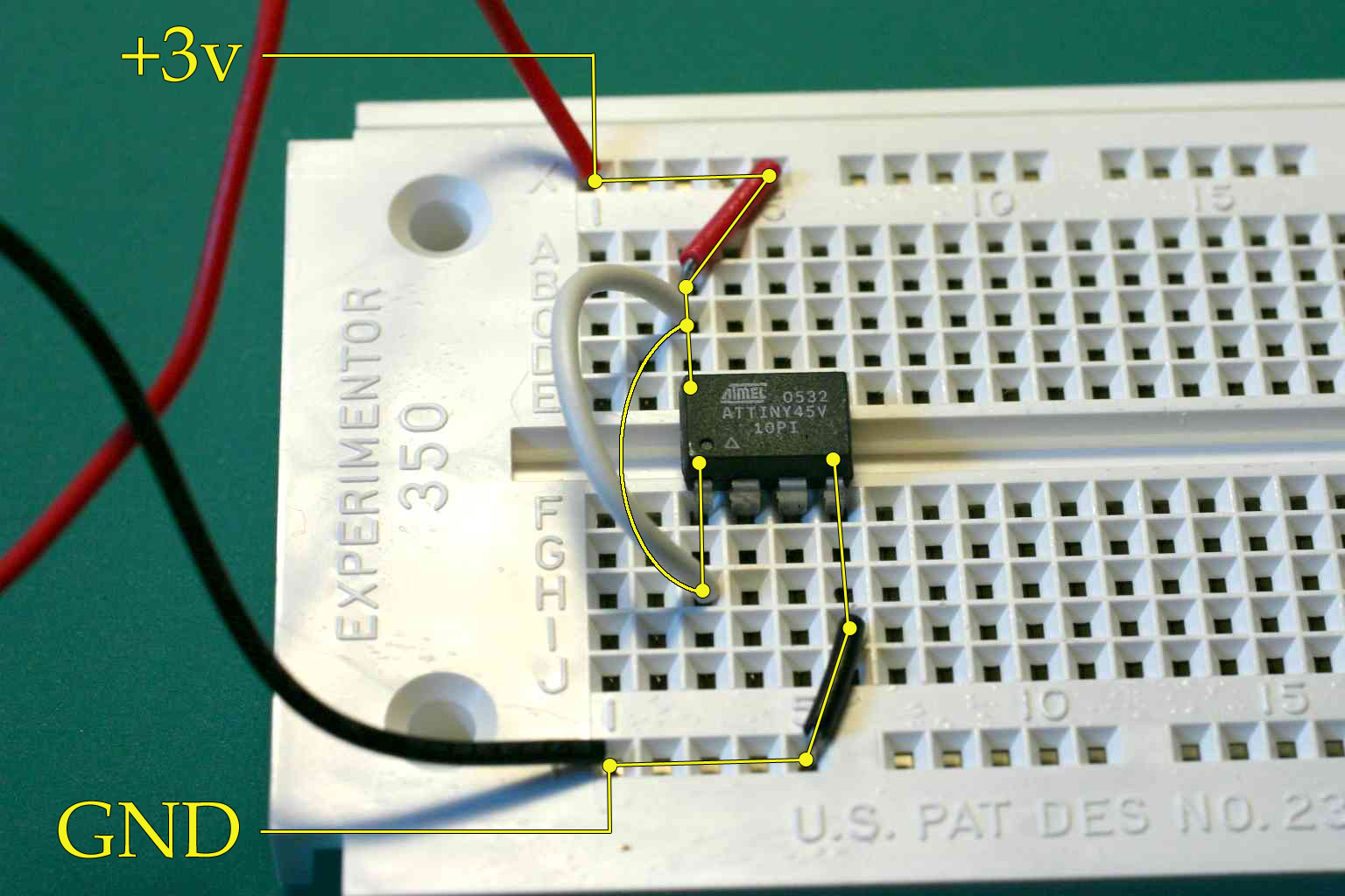
When you become familiar with the connection pattern you will look at a configuration like that on the left and see the circuit sketched on the right (click to enlarge).
This particular circut provides power to a part and signals it to run. The remaining leads will be used to signal information in and out of the part. The white wire can be replaced with a 10k ohm resister which will allow reprogramming the part, in place, using a BreadboardSpider.

Wires that are not expected to move are often cut to exact length and placed close to the board. More frequently moved wires are made with some or even lots of extra length and allowed to loop high over the board where they are easily handdled.
See also MakingJumperWires.
Return to WelcomeVisitors